|
<< Click to Display Table of Contents >> Combined component parts |
  
|
|
<< Click to Display Table of Contents >> Combined component parts |
  
|
With this function, distribution box constructions can be drawn.
Access to the command over: |
AutoCAD/BricsCAD |
Allplan |
|---|---|
Commandline: _EBTCOMB
Assistant: Assistant: Assistant: |
Toolbar: Heating | Heating Design | Toolbar: Sprinkler | Sprinkler Design | |
Start on an already existing distributor position, or scan a distance.

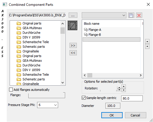
Dialogue-Options
Option |
Description |
|
|---|---|---|
Block register |
The block register path can be edited here.
The block register path is shown here.
All folders, drawings and blocks included in this register are shown and can be selected. |
|
Automatic Flange
|
With this function flanges will placed between the component parts. In the AutoCAD full version select A_Flange PN6-PN16 (armatures 3d), in all other graphic systems choose Flange A (Armatures). Choose the component and define it as a flange by clicking the right mouse-button. |
|
Pressure Level PN
|
The system pressure level can be selected here. The corresponding component part flange diameter will be automatically suggested. The component part length is taken from the table EN558. |
|
Distribution box construction |
Selects the stored distribution box constructions.
Saves the distribution box constructions. Names can now be selected.
The active distribution box sample will be deleted.
The distribution box construction is now shown. |
|
Options |
The active part (shown in blue) can be rotated on the long axis. The rotation can be achieved in the main directions
Rotation (new direction) can be achieved over |
|
Standard Length Centric
|
The center of component part can be set at the second picked point. |
|
Cross Section
|
Controls the active cross section. |