|
<< Click to Display Table of Contents >> Easyline Load-point Ventilation |
  
|
|
<< Click to Display Table of Contents >> Easyline Load-point Ventilation |
  
|
Function to set the Easyline System Load Points.
Access to the command over: |
AutoCAD/BricsCAD |
Allplan |
|---|---|
Command line: _SETLP
Assistant: |
Toolbar: Ventilation | Easyline Ventilation | |
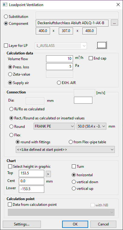
Activate the function, click on one or more load points for the calculation.
Load points can be freely moved, copied or deleted after setting with BricsCAD standard functions.

Option |
Description |
Substitution |
By activating the function, the load point is set as symbol into plan. After unit calculation, the ductwork ends at this point.
|
Component |
An article (block) can be used here.
Function to open the Block selection.
The dimensions of the current selected block will be shown. |
New layer for system |
A new layer and its load point color can be selected. |
Calculation data |
Volume flow The volume flow in m³/h for the load point calculation.
Pressure loss / Zeta-value The pressure loss in Pa or z-value for the calculation. These values can also be entered separately. |
Connection |
All required values for the load point connection.
DN - Field to fix the connection diameter.
Ri/Ro as calculated - The connection to main line is rectangular or round, with the cross section as shown in calculation.
Round - The connection to main line is a round duct.
Flexible - The connection to main line is a flexible duct.
|
Chart |
The load point heights are entered with this function.
A deactivated checkbox allows the load point height to be entered.
An activated checkbox allows the load point height to be set by picking the height coordinates in graphic. Top, center or bottom edge can be used.
horizontal/vertical: The position of the air register can be determined.
|
Calculation point |
Values from a Calculation point will be used. |